3U CubeSat Electrical Power System
Solar array MPPT, battery management, and switched load distribution on a single PC/104 board sized for a 90-minute low-Earth orbit.
Overview
An EPS is the one board on a spacecraft that cannot be reset by another board. This one collects power from four deployable panels through independent MPPT channels, manages a 2S2P Li-ion pack across an eclipse cycle, and distributes three regulated rails behind latching current limiters so that a single load fault cannot take the bus down.
| Year | 2024 |
| Role | Hardware design and environmental test support |
| Disciplines | Power Electronics, PCB Design, Mechanical & Enclosure CAD |
Battery system trade study
Li-Ion Battery System for 6U CubeSat
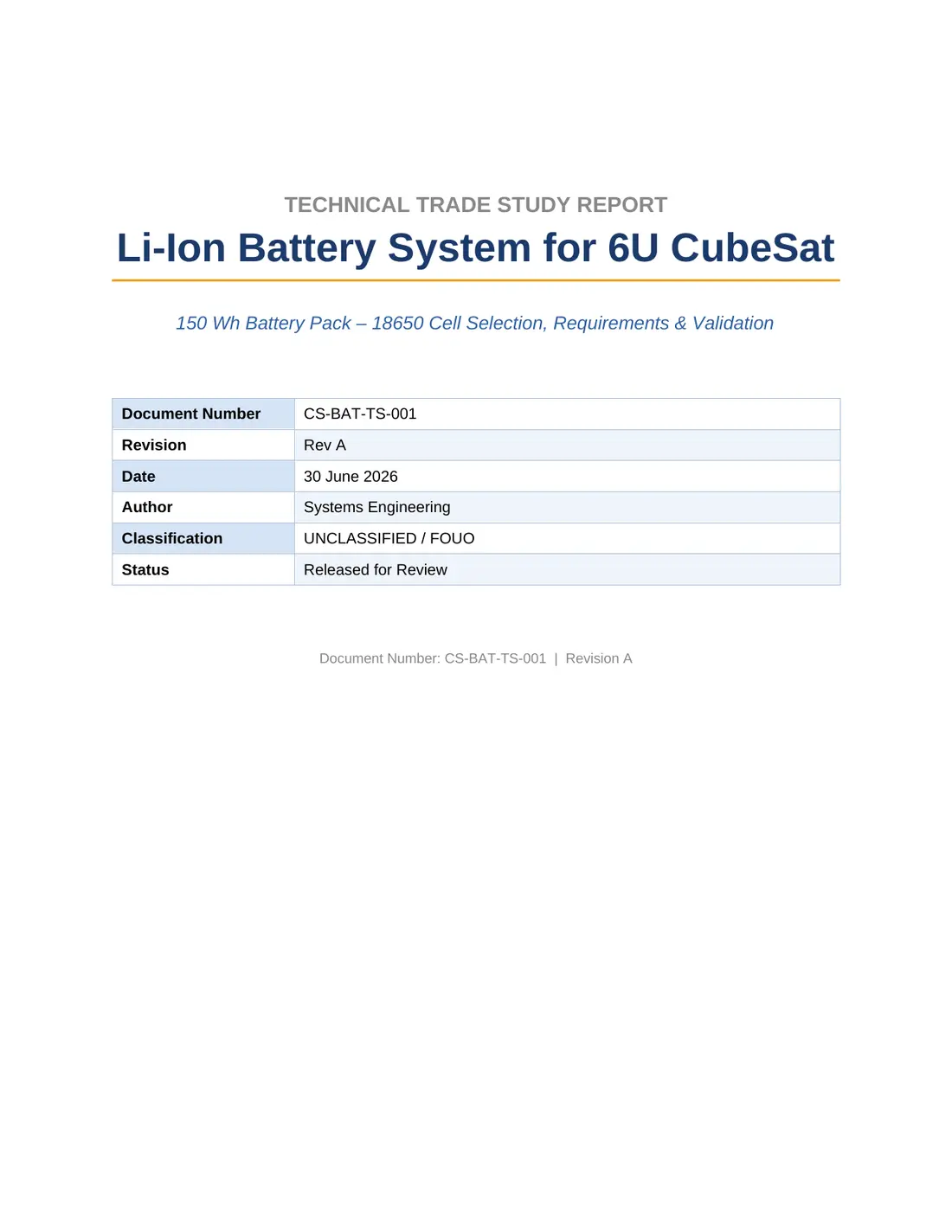
150 Wh battery pack — 18650 cell selection, requirements, and validation
A full trade study for the energy storage side of the power system: four candidate 18650 cells scored against weighted criteria, a pack architecture sized from the orbital energy balance, eighteen requirements traced to the mission need, twenty verification activities, and a risk register.
The selected cell is the Samsung SDI INR18650-50E in a 2S9P arrangement — 324 Wh at beginning of life, derating to roughly 246 Wh at end of life, which leaves 197 Wh usable at 80 % depth of discharge against a 150 Wh requirement. The margin is deliberate: LEO thermal cycling and radiation-induced fade are the two effects that decide whether a pack still meets its number after two years, and both are handled in the risk register rather than assumed away.
| Document | CS-BAT-TS-001, Revision A |
| Date | 30 June 2026 |
| Length | 17 pages, 6 tables |
| Selected cell | Samsung SDI INR18650-50E (NCA) |
| Configuration | 2S9P, 18 cells, ~320 g |
| Energy | 324 Wh BOL / ~246 Wh EOL |
| Sections | Trade study, architecture, requirements, validation, risk |
Architecture
Each panel string gets its own boost MPPT channel rather than a shared bus converter, because partial illumination during tumble makes a single global maximum-power point meaningless. The channels feed a common unregulated battery bus; the battery sits directly on that bus with a protection and balancing front end, and every downstream rail is generated from it.
Key specifications
| MPPT channels | 4 independent, perturb-and-observe |
| Array input | 4 – 9 V per string, 2.5 A max |
| Battery | 2S2P Li-ion 18650, 38 Wh, balanced |
| Bus | 6.0 – 8.4 V unregulated |
| Rails | 3.3 V / 3 A, 5 V / 3 A, 12 V / 1 A |
| Load switches | 8 latching, telemetered, individually resettable |
| Telemetry | Per-channel V, I, and temperature over I²C |
| Environment | −30 to +60 °C, TVAC and random vibe tested |
Select a numbered marker for the design rationale behind that region.
Energy balance
The design case is a 90-minute orbit with a 35-minute eclipse and a worst-case beta angle. I modelled panel output against attitude, subtracted the load profile duty cycle by cycle, and sized the pack so that depth of discharge stays under 20 % in the worst orbit — which is what actually sets pack size, not average power.
Qualification
Questions about this design? I am happy to walk through the trade studies, the measurements, or anything I glossed over here — drakeajoseph@gmail.com.